
제품 상세보기 SINOPRO MAX
Home > 제품 상세보기
제품 상세보기

)
)
)
)
)
- Product:
- MIHW-200-160CH Technical specification
- Product No.:
- SP-MIHW-200-160CH
- Brand :
- SINOPRO
DESCRIPTION
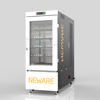
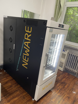
Product name: Temperature Test Chamber SP-MIHW-200-160CH

SPECIFICATION
|
1.2 Model naming rule |
|
MHW |
- |
200 |
- |
2 |
- |
8T |
S |
- |
220V |
|
|
① |
|
② |
|
③ |
|
④ |
⑤ |
|
⑥ |
|||
|
①Temperature Chamber Series |
||||||||||||
|
② Inner litre:200L |
||||||||||||
|
③2:2 layers structure(1 layer not to display as default) |
||||||||||||
|
④8T:8 temperature zones |
||||||||||||
|
⑤Refrigeration mode: S:Semiconductor refrigeration (temperature range:15℃-60℃) Compressor refrigeration not to display as default ( temperature range:0℃-60℃) |
||||||||||||
|
⑥220V:220VAC |
||||||||||||
|
2、Application |
Constant temperature test of cylindrical batteries and 3C pouch cell batteries. Apply to electricians, electronics instrumentation, materials, semiconductors, etc. It is a reliability testing equipment for battery performance test by new energy enterprises and scientific research institutes. |
|||||||||||
|
3、Testing Material Limit |
Strictly forbidden to test or storage in below situation: Inflammable, explosive and volatile materials Corrosive material Biological sample Strong electromagnetic emission source Radioactive substance Extremely toxic substance Anything that can produce above substance or material |
|
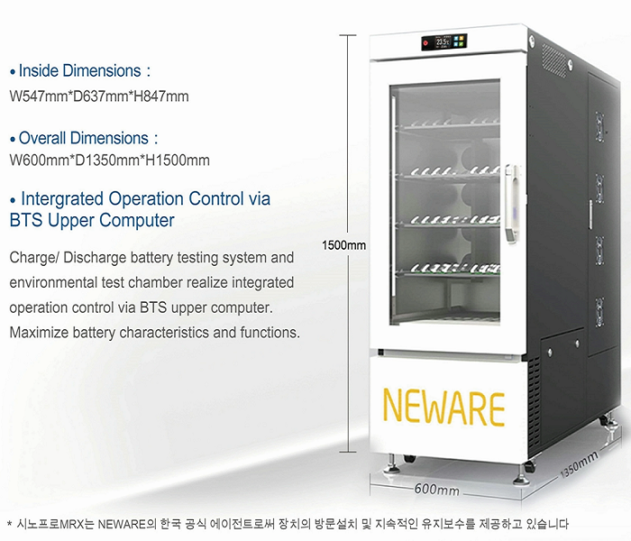
4、Volume and Dimension |
|
|
4.1 Internal volume |
200L |
|
4.2 Internal dimension |
W500 mm×D500 mm×H800 mm |
|
4.3 Overall dimension |
W600 mm×D1350 mm×H1500 mm |
|
5、Performance |
|
|
5.1 Testing environmental condition |
Ambient temperature:+25℃ Relative humidity≤85% No sample in the test box (No loading) |
|
5.2 Temperature range |
0~60℃ |
|
5.3 Temperature range |
≤1℃ (No loading, stable temperature) |
|
5.4 Temperature deviation |
±2.0℃(No loading, stable temperature) |
|
5.5 Heating time |
25℃→60℃ ≤30 min |
|
5.6 Cooling time |
25℃→0℃ ≤50 min |
|
6、Structure |
|
|
6.1 Heat Preservation |
Outside material: High quality cold-bonded steel plate, surface spray and paint treatment Inner material: Stainless steel SUS304 Cabinet heat preservation material: Rigid polyurethane foam(insulation thickness: 50mm) |

|
6.2 Air conditioning |
Axial flow fan、heater, evaporator |
|
6.3 Standard configuration |
Box door: hollow anti-fog tempered glass + stainless steel frame Connecting hole(with soft rubber plug): 4 holes with φ80mm diameter Caster: 4 Sample layer: Sample layer with high temperature resistant electric insulation ; Loading bearing (evenly distributed):10kg/ layer Lighting: 1 pcs |
|
6.4 Control panel |
Touch control buttons |
|
6.5 Heater |
Stainless heating pipe Heater control mode: contact-free equiperiodic pulse width adjustment, SSR (solid state relay) |
|
7、Refrigeration System |
|
|
7.1 Refrigeration compressor |
Fully enclosed compressor |
|
7.2 Cooling mode |
Air cooled |
|
7.3 Throttling device |
Capillary |
|
7.4 Refrigerant |
R134a |
|
7.5 Welding process |
Nitrogen-filled shielded welding |
|
8、Control System |
|
|
8.1 Controller |
LED digital display + touch key controller |
|
8.2 Setting method |
touch-key |
|
8.3 Controlling method |
Forced circulation ventilation balance temperature regulation method. The control system controls the output of the heater according to the set temperature value through the PID automatic calculation output result, so as to achieve dynamic balance. |
|
8.4 Communication |
Ethernet standard interface |
|
8.5 Temperature control module |
Independent research and development (through high and low temperature impact, vibration and EMC and other related reliability performance testing) |
|
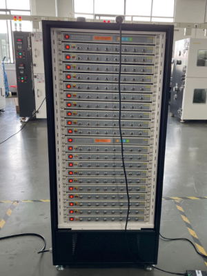
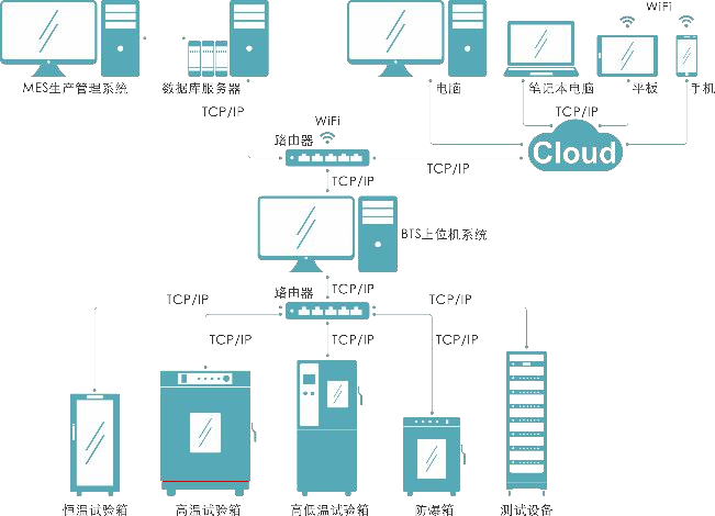
9、The connection between chamber and battery tester |
|
|
9.1 Equipment hardware connection |
battery testing machine and testing chamber connect through the channel cables and communications cables. |
|
9.2 Connection diagram |
|
|
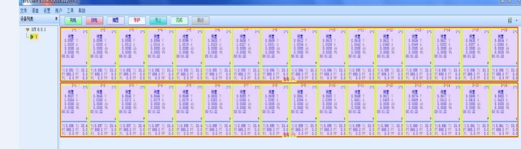
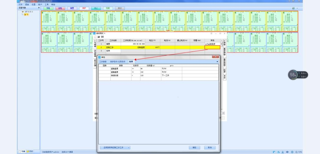
9.3 Control chamber in Neware BTS software |
Step 1: Open client software
|
|
|
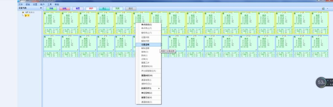
Step 2: Select “Set chamber”
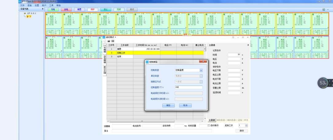
Step 3: Enter the chamber No. you want to set Step 4: Set the chamber control temperature
|
|
|
Step 5: Set step control condition
|
|
10、Safety protection configuration |
|
|
Testing chamber |
leakage protection、short circuit protection |
|
11、Other configurations |
|
|
11.1Power cables |
(1 phase + protective ground wire)1-wire cable |
|
11.2Main power leakage circuit breaker |
1 phase + protective ground |
|
12、Transportation |
|
|
Dimension |
W600 mm×D700 mm×H1300 mm (Without package) |
|
13、Condition of usage ( Prepared by customer) |
|
|
13.1 Installation Requirement |
Smooth land,flatness≤5mm/2m,well ventilated
No strong vibration or strong electromagnetic field around the equipment. No inflammable, explosive, corrosive and dust around the equipment. Proper use and maintenance space should be left around the equipment. The opening door of the equipment should have a space where the door can be opened and closed normally, and there is no other object in front of the door. |
|
13.2 Environment conditions |
Temperature:5℃~35℃ Relative humidity: ≤85% Air pressure: 86kPa ~ 106kPa |
|
13.3 Power supply conditions |
AC(220±22)V (50±0.5)Hz Single phase + protective ground Protect the earth grounding resistance less than 4 Ω |
|
Power Distribution power Maximum current |
The user is required to equip the equipment with an air or power switch of corresponding capacity at the installation site, and the switch must be independently used by the equipment 2kW10A |
|
13.4 Others |
Please do not open the chamber’s door too often, it may affect the testing temperature in chamber |
|
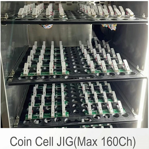
14、Battery Specification and placement mode |
|
|
14.1Battery Specification |
Cylindrical battery |
|
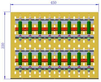
14.2 Battery placement |
4 layer placement, each has 1 fixture panels, each fixture panel is 16CH |
|
14.3 Sample layer (can be customized ) |
|
|
The sample stand is made of resistant electric insulation material |
The cylindrical fixture panel is placed flat on the sample rack of the chamber, and ventilation holes are designed on the fixture panel. |
|
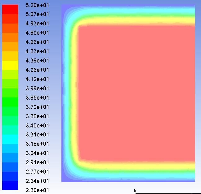
15、Simulation diagram when the temperature in the chamber is running stably(Only for reference) |
|
|
No-load running |
|